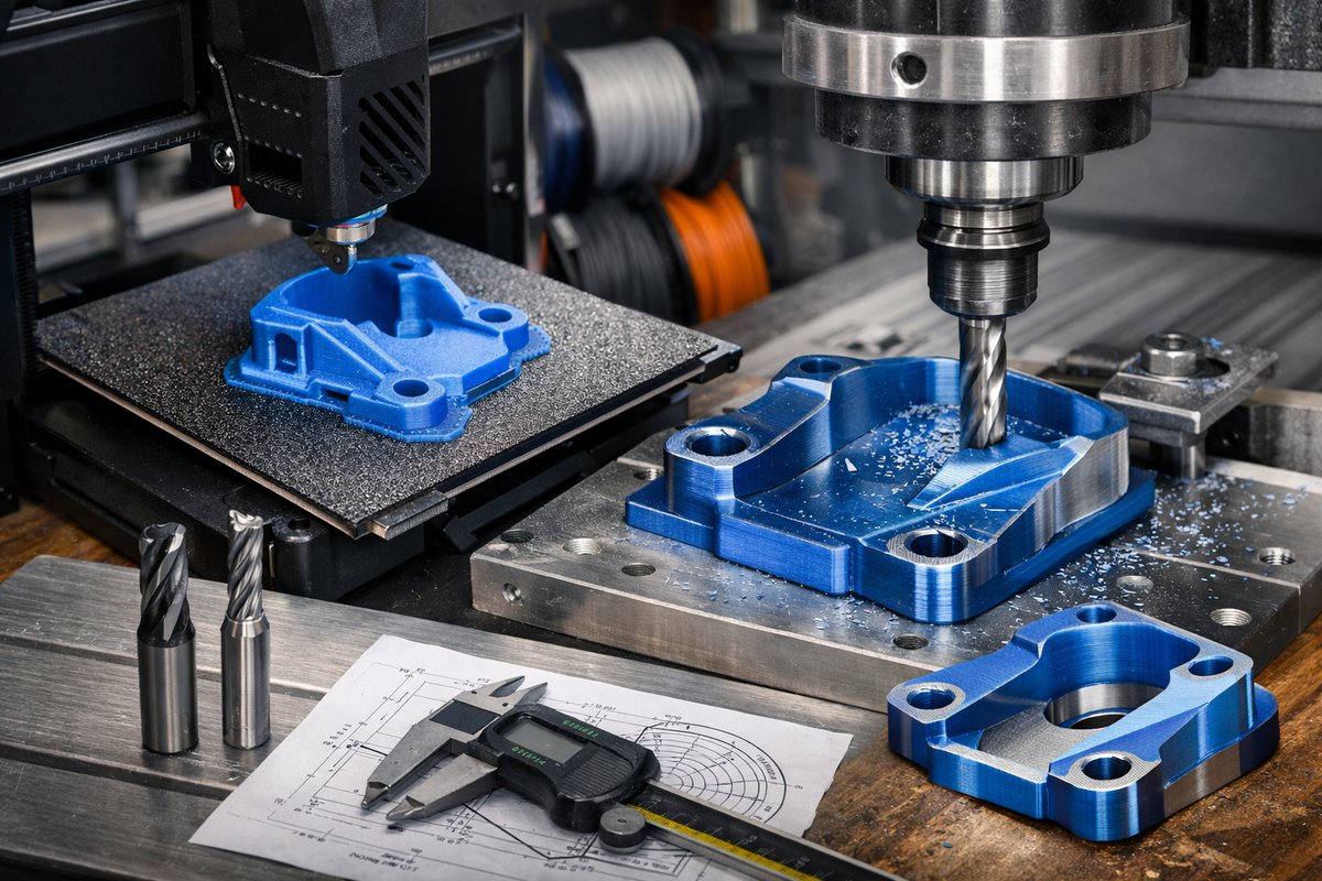

In a workshop where plastic layers rise in quiet formation and high-speed bits carve away excess, a new kind of craft emerges. This approach fuses the freedom of additive manufacturing with the discipline of subtractive machining. You can watch an FDM printer build a complex geometry in hours, then mount that part to a small-format CNC router to achieve crisp edges, uniform surfaces, and precision down to tenths of a millimeter. This guide will introduce you to the tools and steps required to marry these two worlds-and spark the curiosity to explore further.
Every successful hybrid project starts with tool selection. On the additive side, choose a desktop FDM printer capable of reliable layer adhesion and stable bed heating. A flexible build plate and all-metal hotend let you print materials ranging from standard PLA to tougher blends. For subtractive finishing, a benchtop CNC router with at least 300 mm of travel and a spindle speed of 10,000 RPM or more will handle most tasks. Carbide end mills in ball-nose and flat-end profiles, alongside a reliable workholding system-such as adhesive fixtures or modular clamps-form the backbone of your post-processing station.
Preparing your 3D model for hybrid manufacturing begins in your CAD and slicing software. Design with subtractive access in mind: avoid deep internal cavities unless you plan for collapsible cores or later assembly. In your slicer, set a layer height between 0.2 mm and 0.3 mm for a balance of speed and finish. Infill of 20-30 percent gives enough core support while limiting material use. Activate features like coasting or pressure advance if your firmware supports them-these reduce oozing and help the CNC take over with a smoother surface to reference.
Printing isn’t just “press start”; orientation and support strategy matter. Rotate parts so critical surfaces face up, minimizing stair-stepping that even a CNC can’t fully erase. Support structures should be easy to remove by hand or with flush cutters, leaving minimal nub marks. Once the print completes, allow time for the build plate to cool fully. Peel gently, then use a scraper designed for plastic to avoid gouging the part. Inspect the print for layer shifts or voids-those flaws must be addressed in a reprint rather than by heavy cutting.
Next comes the hand-tool cleanup. Use needle files or a flexible sanding pad to knock down any remaining support scars. A light pass with 220-grit sandpaper across the entire surface evens out tiny ridges. Wipe away dust with a soft brush and, if needed, a quick dip in isopropyl alcohol to remove oils from handling. Avoid aggressive solvents on PLA; they can deform thin walls. The goal here is a consistent baseline before mounting the piece on your router.
Workholding requires both stability and protection. Affix a sacrificial MDF spoilboard to your CNC bed and mount a sheet of double-sided tape or a thin layer of adhesive spray. Position the part so you can machine all exterior faces in one or two set-ups, minimizing re-fixturing error. Use a digital caliper to verify part height and dial indicator to ensure the spoilboard sits flat within a few thousandths. This careful alignment pays off when you begin your first roughing pass.
Set up your roughing toolpath with a 6 mm flat-end mill. A cutting depth of 1-2 mm per pass at a feed rate of 600 mm/min and spindle speed of 10,000 RPM works well on PLA and PETG. Engage climb milling to reduce chip-buildup and heat. Maintain a step-over of 40 percent of the tool diameter to clear material quickly without overloading the cutter. Listen for consistent chip ejection-tiny plastic curls rather than melted residue. Adjust speeds and feeds if you hear chatter or see smearing.
After the roughing passes, switch to a 3 mm ball-nose end mill for finishing. This smaller tool reaches crevices and leaves a matte, lightly textured surface that’s easy to paint or seal. For a mirror-like finish, slow your feed to 300 mm/min and take a 0.2 mm depth of cut. Tight radial step-overs around 10-15 percent let the cutter sweep across each layer line, erasing it in smooth arcs. Keep coolant dry-compressed air bursts help clear chips and prevent heat buildup in plastic.
Once machining completes, power down the spindle and inspect the part under bright shop lights. Feel every edge and surface for uniformity. Minor tool marks can be removed with 400- to 600-grit wet-dry sandpaper and gentle hand sanding. If you plan to paint or apply a clear coat, clean the part again with isopropyl alcohol and allow it to dry fully. A thin primer coat hides micro-defects and establishes a key for paint adhesion.
Common issues include part movement during cutting, which shows as ghost lines or ripples. If you see this, increase your holding pressure or add mechanical clamps at opposite corners. Excess heat can cause edge rounding-lower spindle speed or add pauses to let the plastic cool. If layers delaminate under cut forces, rethink your infill density or wall thickness on the next print. Hybrid manufacturing is iterative: each project teaches you a little more about material behavior and tool dynamics.
By blending additive and subtractive methods, you open new creative pathways. Intricate lattice structures no longer suffer from visible layers, and precision features-mounting holes, dovetails, snap-fits-emerge crisp and reliable. The workflow teaches patience as you learn to respect both the gentle buildup of layers and the decisive removal of chips. Beyond plastic, this approach extends to wax patterns, foam prototypes, and even low-density metals on larger machines.
Embrace the challenge of refinement. Let your workshop be a place of curiosity, where a printed model sparks a new fixture design, and a fresh toolpath refines an evolving part. As you gain confidence in hybrid workflows, you’ll see how additive and subtractive practices aren’t rivals but partners. Together, they unlock precision, efficiency, and the satisfaction of craftsmanship revealed through both addition and subtraction.